



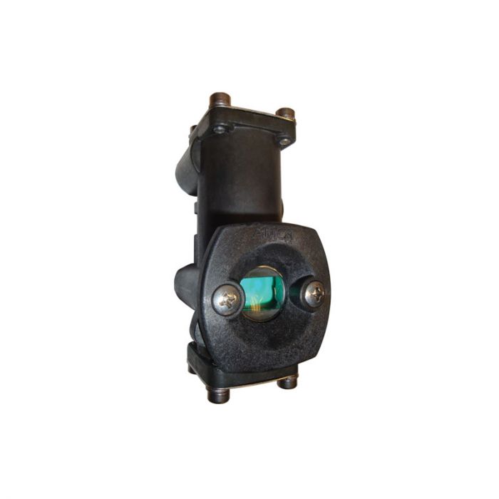
2400M/4400M Pneumatic Space Saver Indicating Relay
The 2400M and 4400M Space Saving Indicating Relays are used in failsafe pneumatic or hydro mechanical control systems. The indicating relays are used in panel systems and sequencing systems and are used to indicate the status of process operating conditions. Normally, an indicating relay is connected to each condition sensing device in a system. The condition sensing devices measure process temperature, pressure, speed, vibration, etc. When in a safe condition, the indicator will show a green indicator. The indicating relays can be linked together to provide first out indication in a system.
Features and Benefits
- 2400M - Anodized (Gulfproofed) aluminum
- 4400M - 316 stainless steel
- Compact size
- Only one moving part
- Wide viewing angle
- Easy maintenance
- Firt out indication to pinpoint trouble
- O-ring sealed bezel
| Operating temperature: | -26 to 93°C | 15 to 200°F | |
| Flow coefficient: | Indicating relay | Kv = 0.43 | Cv = 0.50 |
| Internal orifice | Kv = 0.017 | Cv = 0.02 | |
| IN Port bypass valve | Kv = 0.48 | Cv = 0.56 | |
| Operating pressure: | Indicating relay w/o trip port lockout | 20 - 125 psi | 140 - 860 kPa |
| Indicating relay with trip port lockout | 30 - 60 psi | 205 - 410 kPa |
- Pneumatic Control Panels
- Compressor Control Panels
- Engine Control Panels
- Wellhead Control Panels
- First-Out Indication
- Fail-Safe Systems
- Sequencing Systems
AMOT Indicating Relays are differential force operated 3-way spool valves with a side viewing window, a special Red (striped) - Green spool and 4 ports. Usually one 2400/4400M is connected to a condition-sensing device. The sensing devices are normally closed 2-way valves which detect undesirable temperatures, pressures, vibration, liquid levels, etc. Sensing valves are connected to the “TRIP” port of each Indicating Relay, and pressure is introduced at the “IN” port. As supply air or gas enters the “IN” port it shifts the spool initially to the tripped position (Red) and continues through an internal orifice out to the sensor. If the sensor is in its satisfied condition (closed), the large end of the piston will be pressurized and the piston will shift into the safe (Green) position.